Featured Post

Click for Links to Cabinet IRs/NAM Captures

Thursday, December 30, 2021

Next Project - Type M2 Attenuator

My next project is an 8 ohm 50W attenuator to use with my tube amps. I came across a reactive circuit by JohnH that has become very popular on the Marshall Amp Forum over the past few years.  Many users have reported positive results in volume reduction while maintaining the integrity of the sound. The M2 design attempts to approximate the speaker impedance curve of a 4x12 cabinet with Celestion Greenbacks with minimal number of components. This reactive first stage of the design is made up of three large resistors and an inductor to achieve 7dB of attenuation. Subsequent attenuation stages are purely resistive networks to bring levels further down.

The attenuation  range of the M2 attenuator in the example build is -7dB to -31.5dB, in 3.5dB steps. My plan is to adapt the concept to achieve a range of -14dB to -38.5dB for my needs. This will be done by using a two fixed 7dB attenuation stages, and three switchable steps of 3.5, 7, and 14dB.

Layout and wiring mockup in AutoCAD.

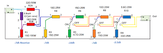
M2 Attenuator wiring modified for my use.
I am using a Hammond 1444-22 chassis to mount all the passive components on the same plane.

Preparing the chassis to be drilled out.

All resistors are from Ohmite/Arcol (100W, 25W) and Vishay Dale (50W). The inductor is a Dayton brand 0.9mH 18AWG air core inductor from Parts Express.

Edit - 1/1/22 - I had to ask users on the Marshall Amp Forum for advice on applying thermal compound on the heat sink resistors. I am hopeful that I’ve applied enough compound for sufficient heat transfer from the resistors onto the chassis.

Resistors populated and (-) wiring soldered.

Edit - 1/2/22 - And it works! The wiring came together fairly quickly. I fired it up with my Jet City JCA22H head on the Overdrive channel with the master volume at about 10:00. At full attenuation, the amp is at low conversation volumes. My 50W Plexi-circuit amp is much louder through the attenuator, at moderately loud TV volumes.

Completed wiring of attenuator.

I put up a Shure SM57 on my Jet City 24SVe 2x12 with a Greenback. I set the attenuator on the maximum -38.5dB setting, and cranked the gain on my Stam SA73 preamp. I was able to record a quick clip sitting 5 feet away from the cabinet with IEMs for monitoring. I need to work on mic placement, but it is an encouraging first step in actually recording the Plexi circuit rather than rely on IRs.

I later played the same riff, but recorded it in 3 different scenarios:
  1. Attenuated heavily and mic’d with a Beyerdynamic M201.
  2. A post-power amp line out. The Suhr Reactive Load acted as a simple line out with the attenuated speaker load connected to the Thru jack.
  3. Through the Suhr Reactive Load, as a separate take.
I made an impulse response of the speaker and mic to apply to the last two setups. I am satisfied with any of the methods to tame the 50W Plexi circuit. It is more satisfying to put up a mic myself and hearing the speaker in the room as I record. Having the option of applying IRs after the fact is a flexible way to work. I originally thought about installing a line out into the attenuator, or buying a line out box from David Bray Amps. Then I remembered that the Suhr Reactive Load already offered this functionality in a transformer isolated flavor. 


Edit - 2/27/22 - I hastily recorded some guitar tracks using the attenuator between my Winfield Typhoon head and my Eminence 1x12 loaded with a Weber Blue Dog. 14dB of attenuation got the 5W amp down to comfortable low volumes for recording.


To be continued…

Friday, December 3, 2021

5E3 Head Build Power Up

5E3-inspired head chassis with tubes installed.

I fired up my 5E3 head build after my final sanity checks. I connected it to my Suhr Reactive Load into my DAW as my bedtime approached. I was relieved to get a healthy, low noise signal. I used my Monoprice guitar with GFS Mean 90s as my test guitar and the P90 noise was tolerable even with all the EMI and dirty power.

I installed typical modern tubes:

  • V1: EH 12AY7
  • V2: EH 12AX7
  • V3 and V4: JJ 6V6
  • V5: JJ 5Y3GT

With a wall voltage of 121VAC, the measured DC voltages off the three 22uF filter caps were 382V, 329V, and 241V. This is perhaps a little bit higher than the desirable range for a 5E3 circuit (350-370V).

I recorded a quick open chord passage using my Monoprice Indio Classic V2 guitar with GFS Mean 90 bridge pickup. The first pass uses a Weber Ceramic Blue Dog SM57 impulse, the second pass a GA10-SC64 SM57 impulse, and the final pass a C10Q M201TG impulse. The tone knob was maxed and the bright volume was set at 12:00. I still have a lot of the nuances of the amp to explore, but the basic sound of the amp is great. I immediately knew that the sound of the 5E3 circuit was more to my liking than the 5F1 circuit.

I will mainly be playing this amp loaded down and with IRs applied for now. I like how the amp sounds with the Ownhammer 1012 TWEED and York Audio VLUX 210 P10R libraries. I will have to dig deeper into the older Redwirez and Ownhammer libraries that I have to find IRs that I like. I may look into the CabIR.eu and Tone Junkies Tweed libraries the future.

Edit -12/8/21 - I had read about the interactive controls of the amp, but did not expect some of the more extreme results. I came across the so-called “better than blackface” setting by turning the unused normal channel volume to maximum or almost that value. This dropped the gain of the bright channel significantly: the amp can stay clean up to about 12:00 with bridge PAF-level bridge humbucker guitar on the bright channel when dialing back the tone knob. The amp is otherwise breaking up by about 9:00-10:00 on the volume dial. I would imagine that there would be even more headroom with a single coil guitar, and will try soon.

Edit - 12/21/21 - I had to reflow the solder on the V3 heater pin 2. I noticed that the tube wasn't glowing when playing through the amp the other night. The amp sounded a bit off, and it looked like there was asymmetrical clipping from looking at recorded waveforms.

Difference in positive and negative parts of waveforms. 

I did not get a dropped voltage on V3 pin 3, but rather the full B+ of 378VDC at the time. I believe that this is a recent development, since both power tubes are typically glowing. It must have been a bad solder joint on the tube pin eyelet itself. I perhaps narrowly averted disaster before I blew the output transformer, or burnt out other components.

Once I verified continuity on all filament tube socket pins, I powered up took down all relevant voltages using a cheap Tenma multimeter. I will check the voltages again with a calibrated Fluke 289 meter.

Voltages measured at tubes.


B+ voltages 

My B+ measurement was lower this time around. Perhaps this means that there was a problem further back in time. The wall voltage was lower by 1VAC this time however.