Featured Post

Click for Links to Cabinet IRs/NAM Captures

Thursday, December 30, 2021

Next Project - Type M2 Attenuator

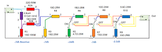
My next project is an 8 ohm 50W attenuator to use with my tube amps. I came across a reactive circuit by JohnH that has become very popular on the Marshall Amp Forum over the past few years.  Many users have reported positive results in volume reduction while maintaining the integrity of the sound. The M2 design attempts to approximate the speaker impedance curve of a 4x12 cabinet with Celestion Greenbacks with minimal number of components. This reactive first stage of the design is made up of three large resistors and an inductor to achieve 7dB of attenuation. Subsequent attenuation stages are purely resistive networks to bring levels further down.

The attenuation  range of the M2 attenuator in the example build is -7dB to -31.5dB, in 3.5dB steps. My plan is to adapt the concept to achieve a range of -14dB to -38.5dB for my needs. This will be done by using a two fixed 7dB attenuation stages, and three switchable steps of 3.5, 7, and 14dB.

Layout and wiring mockup in AutoCAD.

M2 Attenuator wiring modified for my use.
I am using a Hammond 1444-22 chassis to mount all the passive components on the same plane.

Preparing the chassis to be drilled out.

All resistors are from Ohmite/Arcol (100W, 25W) and Vishay Dale (50W). The inductor is a Dayton brand 0.9mH 18AWG air core inductor from Parts Express.

Edit - 1/1/22 - I had to ask users on the Marshall Amp Forum for advice on applying thermal compound on the heat sink resistors. I am hopeful that I’ve applied enough compound for sufficient heat transfer from the resistors onto the chassis.

Resistors populated and (-) wiring soldered.

Edit - 1/2/22 - And it works! The wiring came together fairly quickly. I fired it up with my Jet City JCA22H head on the Overdrive channel with the master volume at about 10:00. At full attenuation, the amp is at low conversation volumes. My 50W Plexi-circuit amp is much louder through the attenuator, at moderately loud TV volumes.

Completed wiring of attenuator.

I put up a Shure SM57 on my Jet City 24SVe 2x12 with a Greenback. I set the attenuator on the maximum -38.5dB setting, and cranked the gain on my Stam SA73 preamp. I was able to record a quick clip sitting 5 feet away from the cabinet with IEMs for monitoring. I need to work on mic placement, but it is an encouraging first step in actually recording the Plexi circuit rather than rely on IRs.

I later played the same riff, but recorded it in 3 different scenarios:
  1. Attenuated heavily and mic’d with a Beyerdynamic M201.
  2. A post-power amp line out. The Suhr Reactive Load acted as a simple line out with the attenuated speaker load connected to the Thru jack.
  3. Through the Suhr Reactive Load, as a separate take.
I made an impulse response of the speaker and mic to apply to the last two setups. I am satisfied with any of the methods to tame the 50W Plexi circuit. It is more satisfying to put up a mic myself and hearing the speaker in the room as I record. Having the option of applying IRs after the fact is a flexible way to work. I originally thought about installing a line out into the attenuator, or buying a line out box from David Bray Amps. Then I remembered that the Suhr Reactive Load already offered this functionality in a transformer isolated flavor. 


Edit - 2/27/22 - I hastily recorded some guitar tracks using the attenuator between my Winfield Typhoon head and my Eminence 1x12 loaded with a Weber Blue Dog. 14dB of attenuation got the 5W amp down to comfortable low volumes for recording.


To be continued…

Friday, December 3, 2021

5E3 Head Build Power Up

5E3-inspired head chassis with tubes installed.

I fired up my 5E3 head build after my final sanity checks. I connected it to my Suhr Reactive Load into my DAW as my bedtime approached. I was relieved to get a healthy, low noise signal. I used my Monoprice guitar with GFS Mean 90s as my test guitar and the P90 noise was tolerable even with all the EMI and dirty power.

I installed typical modern tubes:

  • V1: EH 12AY7
  • V2: EH 12AX7
  • V3 and V4: JJ 6V6
  • V5: JJ 5Y3GT

With a wall voltage of 121VAC, the measured DC voltages off the three 22uF filter caps were 382V, 329V, and 241V. This is perhaps a little bit higher than the desirable range for a 5E3 circuit (350-370V).

I recorded a quick open chord passage using my Monoprice Indio Classic V2 guitar with GFS Mean 90 bridge pickup. The first pass uses a Weber Ceramic Blue Dog SM57 impulse, the second pass a GA10-SC64 SM57 impulse, and the final pass a C10Q M201TG impulse. The tone knob was maxed and the bright volume was set at 12:00. I still have a lot of the nuances of the amp to explore, but the basic sound of the amp is great. I immediately knew that the sound of the 5E3 circuit was more to my liking than the 5F1 circuit.

I will mainly be playing this amp loaded down and with IRs applied for now. I like how the amp sounds with the Ownhammer 1012 TWEED and York Audio VLUX 210 P10R libraries. I will have to dig deeper into the older Redwirez and Ownhammer libraries that I have to find IRs that I like. I may look into the CabIR.eu and Tone Junkies Tweed libraries the future.

Edit -12/8/21 - I had read about the interactive controls of the amp, but did not expect some of the more extreme results. I came across the so-called “better than blackface” setting by turning the unused normal channel volume to maximum or almost that value. This dropped the gain of the bright channel significantly: the amp can stay clean up to about 12:00 with bridge PAF-level bridge humbucker guitar on the bright channel when dialing back the tone knob. The amp is otherwise breaking up by about 9:00-10:00 on the volume dial. I would imagine that there would be even more headroom with a single coil guitar, and will try soon.

Edit - 12/21/21 - I had to reflow the solder on the V3 heater pin 2. I noticed that the tube wasn't glowing when playing through the amp the other night. The amp sounded a bit off, and it looked like there was asymmetrical clipping from looking at recorded waveforms.

Difference in positive and negative parts of waveforms. 

I did not get a dropped voltage on V3 pin 3, but rather the full B+ of 378VDC at the time. I believe that this is a recent development, since both power tubes are typically glowing. It must have been a bad solder joint on the tube pin eyelet itself. I perhaps narrowly averted disaster before I blew the output transformer, or burnt out other components.

Once I verified continuity on all filament tube socket pins, I powered up took down all relevant voltages using a cheap Tenma multimeter. I will check the voltages again with a calibrated Fluke 289 meter.

Voltages measured at tubes.


B+ voltages 

My B+ measurement was lower this time around. Perhaps this means that there was a problem further back in time. The wall voltage was lower by 1VAC this time however. 

Monday, November 15, 2021

More 5E3 Head Progress

I found some time to finish drilling the Hammond chassis for my 5E3 head. I made some more mistakes (eg. a misaligned input jack), but it didn’t turn out too bad for a hand drilled chassis.

Drilled chassis for 5E3 head.

Progression of populating chassis hardware.

The location of the power transformer’s mounting holes were not as precise as I had liked. I was able to get everything to line up in the end.

Chassis with components mounted.

It may have taken a while to get the chassis drilled, things seem to be moving quickly. I am just about to be ready to start soldering wires onto the components.

Chassis with transformer wiring.

I am using a combination of reference documents to build the amp.

Edit - 11/22/21 - I finished soldering the 120VAC wiring into PT primary. The color coding of the Classictone 40-18066 primary wiring is odd: the line connection is white and white-black, while the neutral is black and black-white. I had to double check the diagrams a few times.

AC input wiring into PT.

I shortened all of the transformer wiring, too hastily. I used a forum post in regards to the Classictone 40-18022 OT phase as reference, only to later find another forum post that contradicted the information.  I traced the 5E3 schematic and looked at the Mojotone instruction manual to double check, and it does look like I botched the wiring. I mistakenly ran the Yellow lead to V3 Pin 3, Green lead to V4 Pin 3. The diagram below is my proposed fix on the speaker jack side. 

Edit - 11/23/21 - I dressed the heater wiring based on typical Marshall-style layouts. My tube socket spacing is tighter than the average Plexi layout, so it was a bit of a nuisance to get done. It’s not as neat as I would like.

Edit - 11/29/21 - I ran all of the preamp wiring off the turret board side and soldered about half of those wires in. Once I have the turret board completely soldered, I will start trimming and routing the wiring onto the various tube sockets, pots, and jacks. 

I see why most 5E3 builds have heater wires installed above the tube sockets rather than along the chassis Marshall-style. The wires for V2 are located in the middle of the typical 5E3 board, while the tube socket itself is closer to one end of the chassis. I will soon commit and hope that I don't screw up the layout of the tube socket wiring.

5E3 turret board wiring progression.

Edit - 12/2/21 - I finished making all the connections to the chassis. I quickly did a continuity check on various connections to make sure that I didn’t have any routing errors. I fired up the amp through my Suhr Reactive Load.

I still need to drill a few holes for the vented cage that will sit above the chassis to complete the amp.

All connections soldered.


Friday, October 15, 2021

Monoprice Indio Classic V2 Pickup Swap - GFS Mean 90s

I jumped on a Monoprice Indio Classic V2 guitar on sale for $84 before sales tax. I’ve been on the lookout for an inexpensive HH guitar to stick my unused GFS Mean 90 humbucker-sized P90 pickup set into for a while now. I previously had these pickups in my Ibanez SZ520QM and enjoyed the tones from all positions.


Monoprice Indio Classic V2 prior to pickup swap.

I wasn’t particularly inspired by the sound when I initially played through my HX Stomp. I am hoping that the pickup swap will change that. The nut is a bit sloppily cut, and I may address it in the distant future. The frets are a bit rough when bending strings, so a good polish is in order.

Stock control cavity.

I quickly took a peek inside the control cavity to see what I would be dealing with. The pots were measured to be under 500kohm, at approximately 440kohm. I may reuse the pots, pickup switch, and jack. The tone cap is a 0.047uF, which I plan on swapping out for an Orange Drop 0.022uF cap that I have as a spare part. I will shield the control cavity with copper tape.

Edit - 10/25/21 - I took out the stock pickups in the guitar. The stock bridge and neck humbucker DC resistances measured 15.42kohm and 8.14kohm respectively. The bridge humbucker was fairly hot and strident for my tastes. The neck pickup wasn't too muddy for such a cheap guitar.

GFS Mean 90 wiring splices insulated with electrical tape.

I cut the stock pickup leads about 1.5" away from the pickup switch, and spliced with the leads of the Mean 90s. I didn't have all of the materials (heat shrink, copper tape) to fully complete the installation. I insulated the hot conductor splices with 3M Super 88 tape, then wrapped the overall splice.

Mean 90 wiring, excerpted from this TalkBass post.

The bridge Mean 90 (8.76kohm DCR) is much lower output than the stock bridge humbucker, and much more suited to my tastes. The bridge position is more low mid heavy and not as aggressive as the Wolfetone Meaner P90 in my SX Hawk guitar. The neck Mean 90 (7.95kohm DCR) provides an open, uncompressed sound in comparison to a typical neck humbucker. The tone of a P90 neck pickup with higher gain is much preferable to me than a humbucker.

The only downside to these P90 pickups is the hum. The middle position is hum cancelling; when switched back to a single pickup, the noise is quite noticeable. I am hoping that shielding the control cavity will lower the buzz that I get when facing a particular direction.

GFS Mean 90 pickup set mounted into Monoprice Indio Classic V2.

Full body shot of guitar with Mean 90 pickups.


Clips to come eventually.

Friday, August 13, 2021

5E3 Lunchbox Head Continued

I’ve been dragging my feet to get started with my 5E3 head build. I finally put in a few orders with Valvestorm and Mouser to get the last few jacks and tube sockets needed for my 5E3 lunchbox amp. I had about an hour to get as much of the tedious drilling done.

Preparing the chassis with my layout.

I committed to my layout and started drilling into the Hammond aluminum chassis. I immediately drilled the board mounting holes to make sure that I did not blow my measurements of the turret board. The board appeared to be laid out in metric units, while my layout was drafted in imperial units. My previous mounting hole layout was off by 1/32” for one of the turret board holes. I was fortunate to have a good fit when I committed to drilling.

Checking the turret board’s fit.

I moved onto punching the octal tube sockets with my Greenlee 1-3/16” hole punch, which went smoothly. By the end of the hour, I had drilled the pilot holes to punch the preamp tube sockets.

Punching the rectifier and power tube sockets.

I plan on finishing the preamp tube socket work next time. The top of the chassis has roughly the same amount of work as the front and rear panels combined. I am not looking forward to the Powercon drilling, since my punch (1-3/16”) is slightly bigger than the recommended connector hole diameter (1-1/8”). The holes for the mounting screws can get a bit too close to the connector hole, as it did on my Plexi build.

Edit - 10/22/21 - I haven't had access to an environment conducive to drilling for a while. I finished drilling the top and the rear sides of the chassis today. I was rushing through the process and made one of the output transformer mounting holes too large, which will have to be remedied with some additional washers. Drilling by hand went smoothly for the most part. The PowerCon chassis hole didn't turn out as well as I had hoped, but will be usable.

Top of drilled chassis,

Drilled hole for PowerCon connector.

I will need about half an hour to drill the front panel. Then the fun part comes with component mounting, and later the anxiety-inducing step of soldering.

To be continued.

Tuesday, August 10, 2021

Line 6 HX Stomp Battery Power with Mission 529M

I recently downsized my HX Stomp pedalboard, after establishing my workflow with the unit. I went to a battery powered solution for both portability and convenience. The goal was to be able to quickly set up the Stomp for playing or for mobile recording without having to think about finding an outlet nearby. Another desire was to take advantage of the Stomp's small size to play through it as much as possible.

HX Stomp with battery concealed underneath.

The Fix Pedalboards FP-7X Pedal Riser (6.75" x 5.125" x1.5") is approximately the size of the HX Stomp. I was able to comfortably fit an Anker 10,000 mAH battery, a Mission Engineering 529M power converter, and a USB coupler underneath the Stomp. 

HX Stomp with Pedal Riser.

The 5V 3A current rating of the Anker Powercore 10000 PD Redux is sufficient for the HX Stomp through USB PD, and provides about 3 hours of power. 

The 5VDC out of the PD output of the battery is converted to 9VDC using the Mission Engineering 529M. I went with the Mission 529M due to the Ionic Audio 5V to 9V converter being unavailable for purchase for an extended amount of time.

Battery cabling under Riser.

The 2.1mm center negative output of the 529M needed a combination of Truetone CYR (reverse polarity) and CL6 (2.1mm to 2.5mm, reverse polarity) adapters to interface with the 2.5mm center negative input of the HX Stomp.

A USB coupler is used to reduce wear and tear on the HX Stomp's USB port.


I keep the HX Stomp in an Apache 2800 case from Harbor Freight.

I hear less background noise through my headphones when the Stomp is running on batteries. Whatever noise I was getting previously was likely due to dirty power, desktop fans, sharing a power strip with multiple pieces of equipment, etc. I don’t know if it comes through on recorded DIs, but it is a much more pleasing experience to be monitoring my signal with less noise.

Edit - 11/1/21 - I was successfully able to power my Steinberg UR44 audio interface using the Mission 529M set on 12V. The UR44 requires center positive DC, which was achieved through a polarity inverting cable. The UR44 is not buss powered through USB2, but the 529M along with the Anker battery should provided hours of operation with phantom power engaged.

Going forward, I plan on doing remote acoustic recording with the UR44 and DI recording with the HX Stomp into my iPad Pro. I can do both without the need for an AC outlet nearby.

Monday, July 12, 2021

Wolfetone Dr. Vintage Pickup Set

I decided to swap out the stock pickups in my Epiphone Les Paul Traditional Pro guitar with a set of Wolfetone Dr. Vintage pickups. I mainly wanted a neck pickup that was clearer than the Alnico Classic Pro, and liked my experience with the Dr. Vintage in my Ibanez SZ520. I wanted to try a lower wind bridge pickup for clean and lower gain tones, and the Dr. Vintage bridge pickup made sense.

Wolfetone Dr. Vintage Set.

The DC resistances of the Wolfetone set (Alnico 2) measured 8.2kohms and 7.6kohm on the bridge and neck pickups respectively. The Epiphone ProBucker 3 (Alnico 2) and Alnico Classic Pro (Alnico 5) read 8.7kohm and 7.7kohm respectively.

Reverse zebra Cellulose Acetate Butyrate bobbins.

I was given the option of the butyrate bobbins and same day winding from order acknowledgement since the glossy ABS plastic wasn’t in stock. The cream butyrate bobbins actually matched well with the cream Epiphone hardware. The bobbins on the stock Epiphone pickups were very glossy in comparison. I went with the 4-conductor option to utilize the existing wiring inside the Epiphone Les Paul.

Stock Epiphone quick connect wiring.

The guitar is a 2017 model, which was equipped with quick connect wiring harnesses in the factory. I wanted to keep the quick connect wiring in the event I ever wanted to swap pickups again. I came across screw terminal adapters for Epiphone pickups by Scirina Engineering on Reverb. The simplicity of the screw terminals was worth the cost over other adapters on Reverb/eBay.

Epiphone Probucker 3 and Alnico Classic Pro removed.

Guitar with pickups removed.

Quick connect adapter from Scrinia Engineering.

The Dr. Vintage bridge emphasizes the higher mids, while the stock ProBucker was rounder in the bass/lower mid range. The Dr. Vintage bridge pickup seems like it will help in avoiding low end buildup in recording. I did like the bigger bottom end of the ProBucker for certain tones. Both bridge pickups were set up to be 3/32" and 5/64" away from the low and high E strings while fretting the 22nd fret.

The Dr. Vintage neck is much lower output than the Alnico Classic Pro, which is advertised to be a higher output and more modern than the ProBucker line. I originally had the Dr. Vintage neck pickup 1/8" away from the strings to match the previous installation of the Alnico Classic Pro, but brought it up to 3/32" to suit my tastes. With such a difference in output, it is difficult to compare. What I disliked about the Alnico Classic Pro neck in the past was how much the low end was pushed, even with the pickup lowered. The Dr. Vintage neck did not push the low end as hard, although I couldn't tell if it was due to a dip in low frequencies or if it was due to the lower output. 

I originally thought I would be keeping the guitar stock indefinitely. I still like the stock pickups for certain tones, and have become familiar with the sound. The Dr. Vintage pickups make the guitar a more balanced instrument, which is what I want.

Clips to come.

Friday, June 11, 2021

OC703 Acoustic Panel


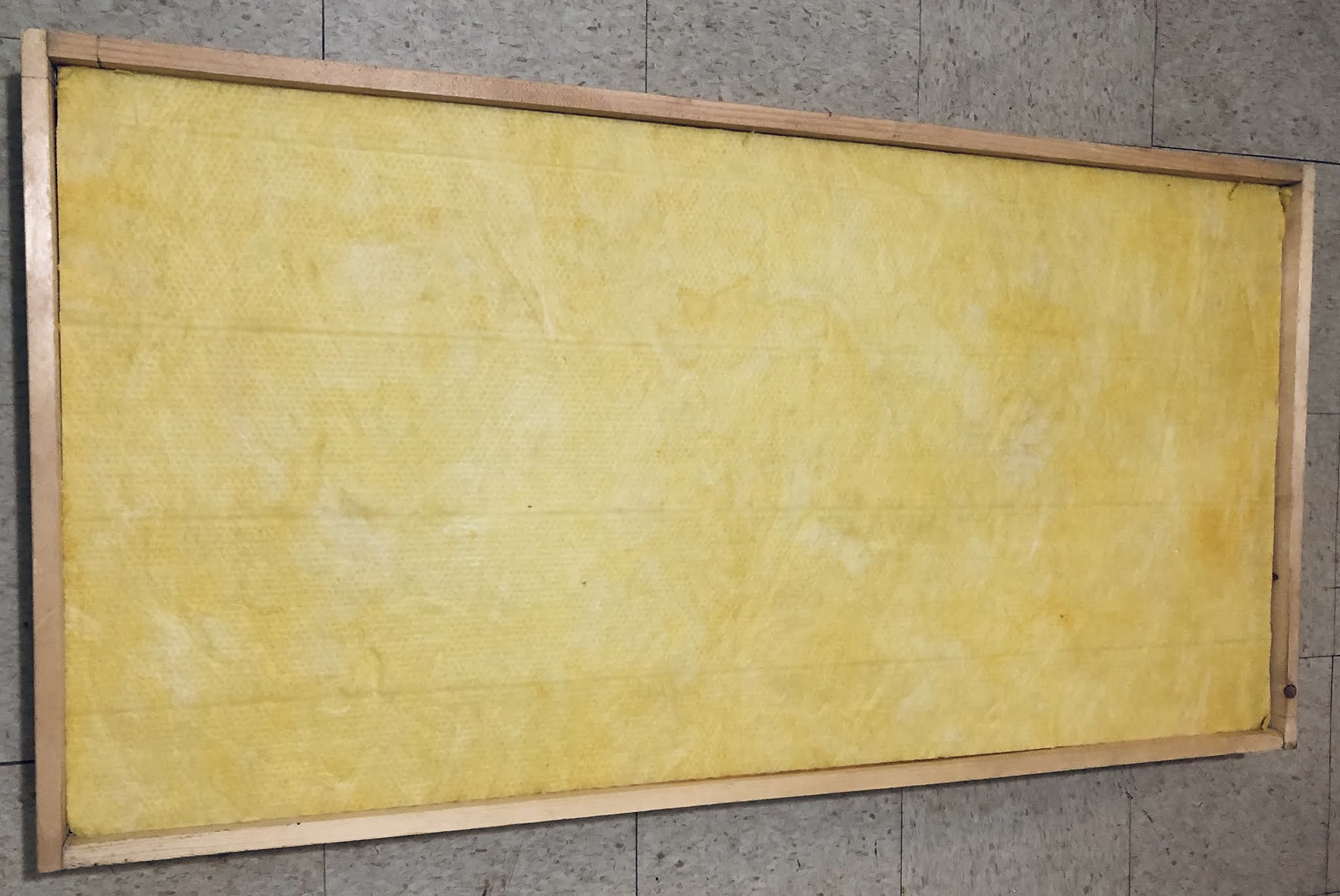
Acoustic panel frame with muslin backing.

I bought a box of Owens Corning 703 2” fiberglass boards a few years back, and had used it to make two 4” thick panels. The two remaining OC703 boards were sitting in storage, as my focus moved on to other DIY projects. I across some leftover 1x5 lumber recently, and pushed myself to use up the OC703.

The joints of the 25.5”x49.5”x4.5” frame were glued and reinforced with corner braces. I stapled bleached muslin fabric onto the frame. I may eventually attach an external frame of 1x1 lumber on the front to hide the staples for aesthetic purposes. It is not a high priority at the moment.

Panel with 4” of OC703 stuffed into frame.

Edit - 10/18/22 - I had some extra white paint to use on the sides of the panel to make it more presentable. I ended up screwing 1”x2” pine strips onto the front face to hide the staples.

Completed 4” thick OC703 panel.

Next, I am thinking of building 6” thick panels with Safe ‘n’ Sound, and soffit-style bass traps with fluffy insulation to  improve my room’s acoustics. 

Wednesday, June 9, 2021

Engineer SS-02 Solder Sucker

Engineer SS-02 Solder Sucker

I recently got the Engineer SS-02 Solder Sucker in the mail. I did not have much luck with a solder wick in the past, although that is likely due to user error. I came across some videos on Youtube which were very helpful in demonstrating how to use the SS-02 to desolder components off PCBs.

The main attraction to this tool is that the silicone tip is rated for 350ºC/662ºF, which can withstand the heat of my typical desoldering work. I can push the tip directly down onto the joint and iron tip without worrying about the solder sucker melting. It looks like the SS-02 is all metal in construction, and will be will durable. I don't know how much it matters that it was made in Japan, but the SS-02 is solid feeling and the design considerations in regards to heat makes it worth the price.

Vox Lil' Night Train C19 clipped, but not desoldered.

Vox Lil' Night Train C19 removed off PCB. Green wire installed in one hole for now.

My first experiment was to completely remove the bright cap C19 on the PCB of my Vox Lil' Night Train head.When I originally modded the amp, I clipped the component without removing it off the PCB. I did not have any desoldering tools on hand at the time, and did not have any luck desoldering the the capacitor off the pads. I was able to get the excess solder off the pads with the SS-02, knowing that I could shove the tip onto the PCB. The PCB holes were clear of solder, with the solder pads intact. I will be adding a switch onto to make a bright cap switchable on this amp.

Now that I am a little more confident in my ability to cleanly desolder through-hole components, I will look into further modifying my Jet City JCA22H head. I would like to install a choke, and see if swapping components to SLO values will be worthwhile. I would like to change out the filter caps in some of my older 80's audio equipment, component swaps I would not consider performing without the right tools.

Thursday, May 20, 2021

Mojotone 12” to 10” Baffle Converter, Eminence GA10-SC64, Jensen C10Q, Jensen C10R

I’ve owned a Roland Cube 60 modeling amp since 2004. I outgrew it once I started getting into playing though tube amps and VST amp modeling. I wanted to separate the amp into a head and cabinet so I could get more use out of the amp. Unfortunately I learned that the Cube 60 baffle cutout was too small for typical 12” speakers. The stock full range Roland Cube 12” speaker is a different shape than a typical 12” guitar speaker.

Roland Cube 60 Cabinet with
Mojotone 12” to 10” Baffle Converter.

I didn’t have a way to cleanly enlarge the hole in the baffle. The easiest option in my mind was to use the cabinet for a smaller 10” speaker. I ran across plywood baffle converters from J Design and Mojotone. I went with the Mojotone, since it was suited for front mounting of speakers. The Mojotone converter comes with 4 keps nuts to hold a 10” speaker onto the converter’s speaker mounting bolts. I bought some slightly longer M4x35mm bolts to mount the converter onto the Cube’s MDF baffle. The stock speaker mounting bolts are M4x25mm.

I will be trying out a Jensen C10Q and an Eminence GA10-SC64 in the cabinet. Based on my encouraging experiences with recording with the Jensen P10R speaker, I want to explore more flavors of 10" speakers with my 5F1/5F2A head and Pro Junior IV. 

If the cabinet records well and I can make some useful impulse responses out of it, then I plan on buying some more 10" speakers to rotate in and out. I will keep the metal grille off, so the front loading of speakers should lead to quick speaker swaps. I am hoping that the front porting and the inside insulation will not significantly impact the sound negatively in a close mic'd scenario.

Edit - 6/11/21 - I loaded the Eminence GA10-SC64 into the cabinet. I finger tightened the keps nuts of the baffle to secure the speaker. I got the feeling that the baffle is actually meant for rear loaded installations, but will proceed with using it as a front loaded cabinet.

Cabinet front loaded with speaker.

2021 Eminence GA10-SC64 Speaker. 

Jensen C10Q.

Edit - 06/25/21 - The GA10-SC64 is very different from the P10R. I am not familiar with the nuances of American-style speakers, since there aren’t as many online audio examples as the British-style speakers. The P10R works well with tweed overdrive, while the GA10-SC64 fares better with cleans for my usage. The GA10-SC64 is not harsh, even with a microphone pointed directly at the center of the dust cap. Blends of my GA10-SC64 and P10R IR captures are pleasing, as the speakers seem to be complementary. 

Capturing GA10-SC64 IRs with a Shure SM57.

The Cube 60 cabinet’s ports don’t seem to exert a negative influence on the sound, so I intend to continue to experiment with more 10” speakers. I would like to eventually try an Eminence Red Fang 10 and a hemp cone speaker, after I familiarize myself with the GA10-SC64 and C10Q.


Edit - 8/29/21 - I swapped in the Jensen C10Q speaker to see how it compares to the GA10-SC64. The swap was quick and painless, as I originally anticipated with the front-loaded exposed baffle. The C10Q is brighter than the P10R and GA10-SC64.


My plans to get a British-flavored 10” speaker with the Eminence Red Fang 10 were dashed when Eminence discontinued the model this summer.

While purchasing a small hardware order for my 5E3 build, I came across a deal on a Jensen C10R speaker at $41 on Tube Depot’s website.


My main interest is to see how this small magnet ceramic speaker compares with the Alnico P10R and larger magnet C10Q.


To be continued.