Featured Post

Click for Links to Cabinet IRs/NAM Captures

Wednesday, June 10, 2020

Sescom SM-1A Direct Box

I bought 2 Sescom SM-1A direct boxes for about $30 in 2013 and 2014 to record direct guitar and bass. I couldn’t find the specifications for my particular units from the 70’s/80’s. By 1990, the SM-1A was on its mkii model and had an input impedance of 60k. This is rather low for guitar DI purposes by modern conventions, but I was happy to play through it at the time with early guitar amp sims (LePou, Ignite Amps, TSE, Nick Crow, etc.). I used a Korg DT10 (1 MOhm input Z) to split/buffer my input occasionally, so I got around the low impedance issue without knowing it. I still like using the SM-1A for bass guitar and synths.

I dug these direct boxes out again and took a peek at the innards.  The transformers look like they are in MuMetal cans.

Different finishes during its production run.

The guts of one SM-1A.

The guts of a second SM-1A.

Edit - 8/9/24 - I pulled out my SM-1A to do some informal comparisons to my typical DI rig in 2024. I typically use a Waves/PRS Guitar Interface into my Steinberg UR824 Audio Interface when I am not using my HX Stomp or Fractal FM3. With these 3 options, my guitar or bass is loaded by a 1Mohm input impedance in all cases.

My first test was to compare how the two chains handled a buffered bass guitar signal. I used my Ibanez Mikro Bass set on the P-pickup (6.27kohm DC resistance). I split my signal using a old Korg DT10 tuner, so the takes would be identical.

One output went to the Waves/PRS Guitar Interface, while the other went to the Sescom DI into a CAPI VP28 preamp. Both chains were within 0.3dB of my usual 11.5dBu DI chain. Once the gain difference was taken care of, the two signals were very similar. The Sescom/VP28 chain is going through a total of four transformers and two 2520-style discrete op-amps, while the Waves/PRS Guitar Interface amplifies the signal with none of these mojo parts.

Ibanez Mikro Bass - Korg DT10 - Sescom SM-1A - CAPI VP28 - Steinberg UR824 Line In

Ibanez Mikro Bass - Korg DT10 - Waves/PRS Guitar Interface - Steinberg UR824 Line In


I then tried the bass directly into each input chain. I had to record separate takes, making it a very flawed comparison. I did recorded multiple passes because I didn't trust my playing to be consistent. Several key differences kept showing up:
  • The signal through the Sescom/VP28 was suddenly 1.7dB louder than through the Waves DI.
  • Even with this gain difference balanced out, there was a frequency response difference. The Sescom chain captured more harmonics differently in the 1-2k range.
  • The direct sound of the bass into the Waves DIs were comparable in level and sound to the buffered examples.
  • The direct sound of the bass into the Sescom chain consistently had more mid-range.
Ibanez Mikro Bass - Sescom SM-1A - CAPI VP28 - Steinberg UR824 Line In

Ibanez Mikro Bass - Waves/PRS Guitar Interface - Steinberg UR824 Line In

Ibanez Mikro Bass - Sescom SM-1A - CAPI VP28 - Steinberg UR824 Line In - 1.7dB trim in DAW

Sescom (-1.7dB) and Waves/PRS different takes compared. 

These observed differences are likely due to the impedance loading presented by the Sescom transformer. The buffered output of the Korg DT10 had likely converted the signal to low impedance, for which both chains interfaced in a similar manner.

The direct bass into the Sescom DI demonstrated weaker impedance matching (6k to 60k), which likely contributed to the change in frequency response. This coloration is probably welcome on bass, but probably detrimental for electric guitar DIs to be processed by amp modeling.



Wednesday, June 3, 2020

Fuzz Pedalboard Build


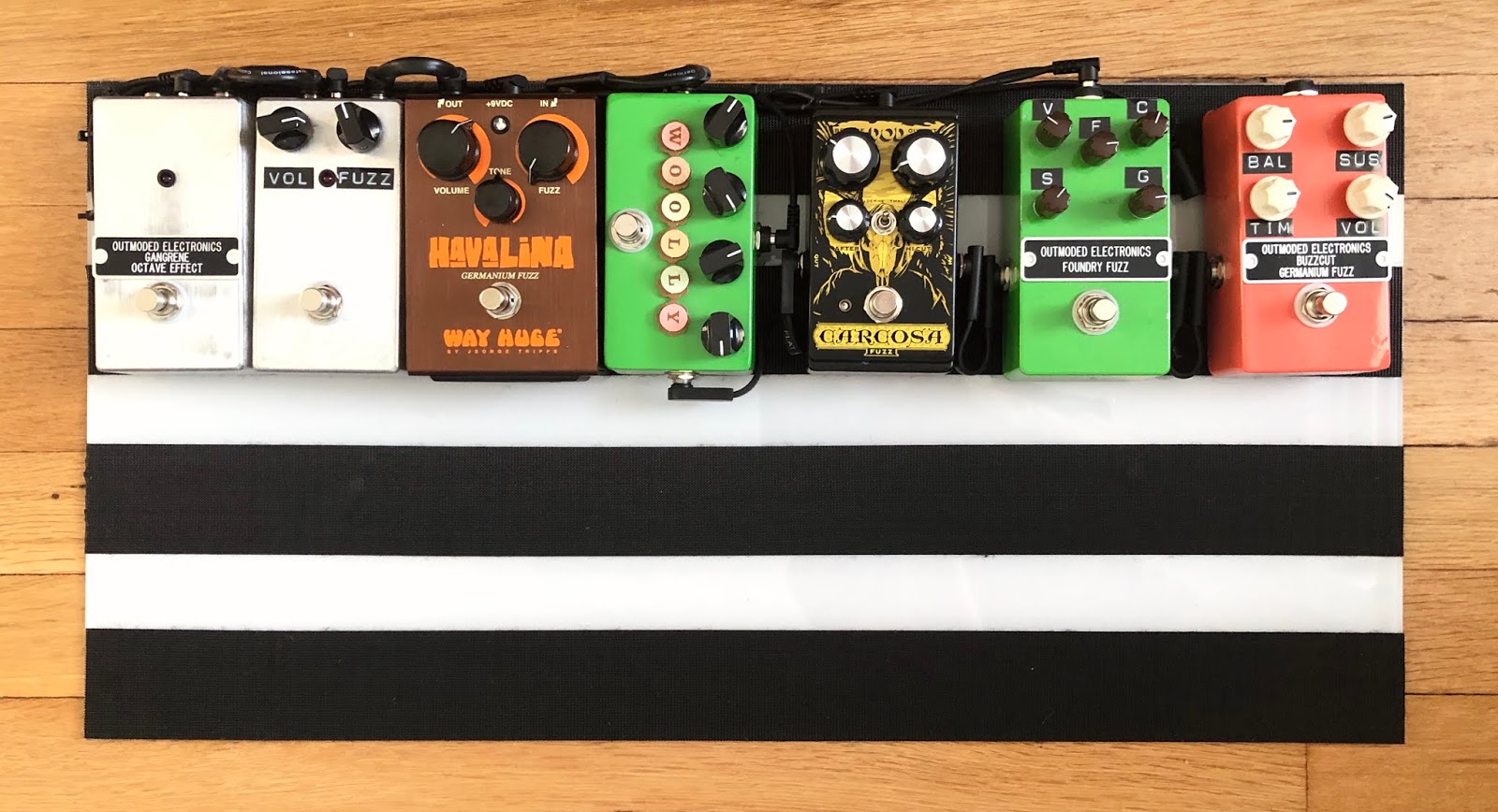
I decided to put my fuzzes all on one board to have as many fuzz textures available at once when recording.

I have so far populated the top row, which will be the A path.
Buzzaround Clone —> Fuzz Factory Clone —>DOD Carcosa —> Woolly Mammoth Clone —> Way Huge Havalina —> Fuzzrite Clone — Green Ringer Clone

Fuzz demo of A path on YouTube


An A/B switch box will have a B path connected to it as well.
The plan for the B path is: Fuzz Face Clone —> Harmonic Percolator Clone —> Companion Fuzz Clone —> Meathead Clone —> Behringer SF300 —> Boss HM-2

The pedals secured using Velcro to a 12”x24” acrylic sheet. An Electro Harmonix pedal bag will house the board.

The Buzzaround is the lone positive ground effect. Two Snark power supplies will be used for the board when needed.

I moved the Havalina and Carcosa off of another pedalboard.

8-12-20 - I finally got an Electro Harmonix pedal bag. The bag holds my pedals and the acrylic sheet fairly snuggly.

I will be housing the PedalPCB Fuzz Face, Companion Fuzz, and Harmonic Percolator clones in a single 1590DD enclosure from Love My Switches. The A/B switch will be built in a 1590BB enclosure with a switchable pickup simulator circuit. 

Almost completed with 2 more pedals to go.

PCBs for Fuzz Face, Harmonic Percolator, Companion Fuzz.

9/8/20 - Drilled pickup simulator enclosure.

11/12/20 - A/B Switch and Pickup Simulator wiring planning.

11/12/20 - An unused twin-blade pickup from EY Guitar Parts will be used to for the pickup simulation box. I will wire the pickup onto an On-On DPDT switch for series-parallel wiring of the pickup. The pickup will be wired to a 500K volume/500K tone control circuit.

I have decided to build a straight PNP Fuzz Face in the 1590DD enclosure, and will save the PedalPCB PCB for a standalone build. I don’t want to take a chance with mixing a charge pump with 12 other fuzzes.

11/20/20 - The A/B switch and in-line pickup simulator was completed today. 

Completed build of in-line pickup simulator and A/B selector.

12/13/20 - The prepping of the Fuzz Face/Companion Fuzz/Harmonic Percolator enclosure has begun. I am hoping that this will be the catalyst for the build to actually get done. The Companion Fuzz and Harmonic Percolator circuits will be powered off the pedalboard daisy chain. I will add a second DC jack to provide an external 9V battery connection via a Voodoo Lab Battery Snap to 2.1mm connector to the Fuzz Face circuit. 

Drill template for the 1590DD enclosure.

.

Tuesday, May 26, 2020

GGG Fuzzrite Build


I recently ordered a Fuzzrite kit from General Guitar Gadgets. I was originally going to build the pedal on vero board as part of a 3-in-1 fuzz pedal.

I used the included 2N3904 transistors, but socketed the Q1 and Q2 positions for when Smallbear reopens their online shop.

The kit came with 2 red Wima 0.0022uF capacitors, which were not great fits on the PCB.

7/15/20 - I received some 2N649 transistors from Smallbear and will do an A/B comparison one day.

Monday, May 18, 2020

Shure M67 Preamp Mod

I purchased a Shure M67 a few years ago with the idea of performing the individual direct out mod. I likely gave up after being overwhelmed by the messy stock wire layout.

I want to give the RodC M67 mods a try, to relocate the gain knob to use the preamp for louder sources. His website was now gone, with a few other sites preserving the information.
  • Channel 1: gain control to be relocated; switchable unbalanced direct out to headphone jack chassis hole.
  • Channel 2: gain control to be relocated; switchable unbalanced direct out to “2” banana jack chassis hole.
  • Channel 3: stock gain; switchable unbalanced direct out to ”3” banana jack chassis hole.
  • Channel 4: stock gain; stock mix bus connection intact.
  • Line Output will be rewired to the Microphone Out XLR jack, with 600 ohms resistance across pins 2 and 3 if possible
I hastily yanked out the headphone jack before I started taking pictures to document the stock wiring.


Stock wiring on switches.


Headphone circuit removed. Balanced output remaining to be removed. 


Edit 6/2/20. I started to make the changes to the output section of the preamp. I spliced the line level tap of the output transformer to the Microphone Out jack. 


I have so far rewired the gain pot of channel 1 to come before the transistor stage. Next will be the wiring of the direct outs.

Edit 6/18/20. I completed performing the modifications to the M67.

The repurposed mix bus output has an 820 ohm and 2.2kohm resistor pair in parallel on pins 2 and 3 for an equivalent load of 597.35 ohms. I can directly connect the mix bus output to a balanced line input and load the preamp properly.

The direct outputs are lower in gain as expected, as the taps are before the final amplification stage. I can understand how relocating the gain pot to attenuate the signal into the transistors is useful for louder sources like drums. 

I currently have the new unbalanced direct outputs of the M67 hooked up to my the RCA inputs of the Roland VSR880 recorder as a few extra channels of mic preamps.

Rear panel with 3 Switchcraft 112BX connectors for channels 1-3 direct outs.

Overall view of chassis.

Direct out jack wiring (black & white twisted wires). 

Lo-cut switches rewired as switchable direct outputs.

Markup of schematic depicting my M67 modifications.

Thursday, December 5, 2019

Squier VM Jaguar Pickup Swap - Fender Pure Vintage 65


I installed a set of Fender Pure Vintage ‘65 Jaguar pickups in my Squier Jaguar. These pickups replace the stock Duncan Designed pickups. The stock Duncan Designed bridge pickup emphasized the mids too much and was too hot for my liking. The difference in the neck pickup was much less apparent. I like aspects of both pickups.

Both Fender pickups measured at 6.55kohm DC resistance.

Video of all pickup selections through a fairly clean amp setting


Video of all pickup selections through crunch amp settings

Tuesday, November 5, 2019

50W Plexi-Style Circuit Build Completed

I started looking into building a bass-spec Plexi circuit started when I first came across the Metro Amp 50W build guide. I read about amps that switched between different Marshall eras, like the Heritage Colonial, Aiken Intruder, Germino Club 40, and Fargen Mini-Plex.

The form factor was definitely inspired by a one-off JTM50 build on the Lil Dawg Amps blog. It showed me that the space spacing layout of a Marshall circuit in a 17” wide head was possible. My lunchbox 5F1/5F2A head was also influenced by his offerings.

The kitchen sink approach to the switching options was mainly based on a Johan Segeborn video demonstrating a Marshall 1987X that  covered several Marshall circuits. I can get close to Bass Spec, Organ Spec, and Lead Spec ('67, '68, '69, '70).

I ordered the following tubes for the amp from Doug's Tubes:

  • V1 - Ruby 12AX7AC5 HG+
  • V2 - Shuguang 12AX7
  • V3 - Sovtek 12AX7LPS
  • V4, V5 - Electro Harmonix EL34

I will explore more fancy tubes in the future, but purchased these to make sure the amp would fire up.

Front panel of the amp.


Front Panel Option Summary:
  • Switchable 470pF mixer capacitors on each channel
    • Either Channel 1 or 2 can be set as the bright channel
  • Channel 1 Bright Cap Select: 500pF, none, 100pF
  • Channel 2 Bright Cap Select: 4700pF, none, 250pF
    • With the Channel 2 mixer cap engaged, I have a shared cathode bright channel with more bright cap options
  • PI Coupling Cap Value Select: 0.022uF, 0.09uF
    • Switchable between Lead and almost Bass spec

Rear panel of the amp.


Rear Panel Option Summary:
  • V1 split/shared cathode switch
  • V1A Cathode Bypass Cap Value Select: 221uF, 1uF, 5.7uF
  • V2A Cathode Bypass Select: 330uF, none, 0.68uF
  • Lead/Bass Tonestack Switch
  • Variable Negative Feedback: 47k to 147k on 8 ohm tap
  • Bias Test Points
Transformers:
Modifications shown on Metro Amp's 50W Plexi Schematic.


Bass Spec: changing through different bright caps.


Lead Spec: Trying out the different switch options.

Lead Spec: All controls at maximum.

Thursday, October 24, 2019

Finishing Up Plexi Build

I finished soldering all of the components and will begin checking all connections prior to the initial power-up.

I have ordered 3 12AX7s and 2 EL34s for testing of the amp next week.

Chassis Wiring

Front panel without knobs.

Rear panel without knob for NFB.

Top view of chassis.

Edit 10/31/19. I successfully powered up the amp with all tubes installed.

V1: Ruby 12AX7AC5 HG+
V2: Shuguang 12AX7
V3: Sovtek 12AX7LPS
V4, V5: Electro Harmonix EL34 matched pair, average distortion

B+ voltage off the HT fuse is nominally 432V, in line with typical '68 Plexi 50W voltages.

Below are some additional photos of the completed amp.
Front view with cage and knobs installed. I will redo the Midde and Treble Dymo labels.

Output section wiring.

Power wiring.

Input section wiring.

Switchable mod wiring.

Tone control wiring.

Initial observations playing through IRs loaded by Suhr Reactive Load:
  • The bright caps increase the noise floor of the amp, especially when the channel has a bright mixer capacitor engaged. Adding gain through the V2A cathode bypass cap does not result in as much noise.
  • Engaging a bright cap with the bright mix capacitor off on the active channel does not increase the noise floor as much.
  • I have 2 near-identical channels in shared cathode mode, by engaging the bright mixer cap for the active channel, and turning it off the the unused channel. I can set up four different bright cap values this way.
  • The 4700pF bright cap (channel 2) immediately distorts the sound as expected.
  • 500pF on a clean sound is too bright, even on shared cathode mode.
  • The lead channel in split cathode mode is noisy when I turn it up to 10. This is more gain than I need, and I am ok with the noise floor when I dial the amp back to 8 (Fender-scale).

Tuesday, September 3, 2019

IRs of Jensen P10R in Pro Junior

Download Link of P10R with Seymour Duncan Powerstage 170 Power Amp

I started shooting impulse responses of the Jensen P10R speaker in my Fender Pro Junior IV.

I have used the following microphones to capture the IRs:

  • Shure SM57
  • Sennheiser E906 (Bass, Flat, and Treble setting)
  • 3U Audio Black CM1
The same equipment was used as my previous impulse response captures  (Steinberg UR44, Stam SA73). Each sweep was 10s long.

Jensen P10R speaker mic'd with 3U Audio Black CM1.


Edit - 12/4/24 - I re-shot the P10R speaker with my Behringer A00 power amp.

Thursday, August 29, 2019

Plexi Amp Build chassis mounting progress

I found some time to start mounting components onto the Hammond chassis. Most of the front panel is populated, as well as a bit of the backpanel.

One of the on-off-on DPDT switches was a dud, but I had luckily ordered a spare.

Progressing panel component and transformer mounting.

A shot of the front panel from the underside.

Shortening some of the transformer leads.

Testing the fit of the main turret board.

Update 9/4/19: more wire dressing and a few solder joints.

Update 9/10/19: I had half an hour to work: layout heater wiring from V5 to V3.  It’s more time consuming than I had imagined. 

Update 9/13/19: Heaters installed. I tried to match the installation depicted in the MetroAmp builder guide.

Update 9/26/19: Input jack wiring, more grounds, filter cap wiring, bright cap switches.

Update 10/16/19: soldered many of the wires on the main turret board side. 

Update 10/18/19: Connected turret board to front panel controls and input jacks, laid out mod components on the turret strips.

AutoCAD layout used for component placement.